
As I have said before, I use a disc of wood to attach the various mechanisms and the whole is mounted on a slim axle, but this is not the answer that Bessler could have used. My method results in a flimsy construction incapable of carrying out the tasks Bessler's did. His method required the construction of a framework as depicted in my original biography about him., see below.

In my original sketch I included eight divisions but things have changed since then. In the first place I envisaged, and still do, two separate wheels, one a mirror image of the other, designed to turn the Kassel wheel in either direction. There might therefore have been a need for only four radial struts; one set for each direction that the wheel turned. Subsequently I proved to my own satisfaction that there were in fact five mechanisms operating inside the wheel and therefore five radial struts required for each direction of the wheel.
The initial framework might have stopped at the half way point, as shown in the illustration above, allowing access easily to the areas close to the axle. The rest could have been added later to complete the construction. I read somewhere, but I forget where that the thickness varied from 15 to 18 inches on the Kassel wheel and I have shown why this might have been necessary above right.
The axle makes an interesting study. Six inches in diameter and six foot long; using a wood weight calculator I found the weight to be estimated at between 50 and 100 pounds dependant on whether it was pine or oak, and there are many other possibilities using other woods, but the weight is significant. There must have been some kind of support for the axle before he even began, unless he used a vise to support it and hold it still. A hundred pound axle would be a heavy object to manoeuvre around and I think it likely that he made a work-bench designed to hold it in position while he worked on it. But the six foot radial arms would become a problem because it would need the support structure to hold the axle six feet above the ground, otherwise the ground would interfere, unless he then added to the final section of each radial arm at a later stage., so I lean towards the three foot segments as the way to begin work on it.
Another thing is the positioning of the three-quarter inch bearings. Any one who has had a bike will be familiar with the way the wheel can become wobbly. How Bessler managed to build his wheel without any reported wobble because the wheel was slightly out of true was an achievement in itself.
How were the radial struts attached to the axle? Perhaps he used dowels sunk into the axle and subsequently used them to provide an attachment. Or maybe there is a clue in the two drawings below, taken from his "Das Triumphans.."
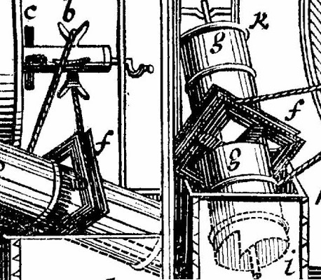
The square box-like structure lends itself as a means of attaching to an axle.
Just some thoughts about the problems he faced building such a large structure on his own.
JC
10a2c5d26e15f6g7h10ik12l3m6n14o14r5s17tu6v5w4y4-3,’.


You have raised many interesting questions in this blog, John. I, too, am concerned with, aside from the actual imbalanced pm wheel mechanism Bessler used, the methods he might have used to construct a wheel and then adjust it. I believe that, most likely, he constructed the vertical supports and axle with its pressed in steel end pivots first. Then, I think he constructed the drum from slats of white oak wood. These slats could even have been glued together with a few nails for reinforcement. Once that very rigid structure was completed, he would have slipped the axle through the center of the drum frame and secured the drum to the axle (this feat was probably a two man operation). Securing the drum to axle was easily done with more glue, corner wedges, and nails. Next, the rim stops, weighted levers, suspension springs, coordinating ropes, and bi-directional latches are installed. Finally, the coordinating ropes were carefully adjusted so that any lever reaching the 9:00 position would be hanging, precisely counter balanced, at a precise angle to a radial line passing through the lever's pivot. At this point the open framework drum was fully operational. However, to conceal his secret mechanism, Bessler covered both sides of the drum with oiled and, most likely darkly dyed, linen. I'm still undecided as to how this fabric was secured to the drum. You mentioned that there was no wobble in any of Bessler's wheels. However, I think I remember there being a report that the Merseberg wheel did have a noticeable wobble to it that caused one of its two vertical supports to rapidly jump or "hop" up and down inside of the wood pieces nailed to the floor and ceiling which helped keep the vertical supports in position. I have not been able to find a reference for this, though.
ReplyDeleteIf he glued and nailed everything else, would it not be reasonable to presume that he glued and/or nailed the fabric?
ReplyDeleteThat's quite possible. Perhaps he used large 6 foot long rolls off dyed linen and then cut 6 x 12 foot sheets from these. These sheets would have been stretched over and held down on a 12 foot diameter drum (which rested on the floor on one of its sides) to which a slow setting glue had been applied to its rim. When the glue dried, any overhanging pieces of linen would have been trimmed away to tidy things up. Perhaps as the glue dried, Bessler nailed tacks around the rim of the drum for further reinforcement. Then he would have cut out various inspection holes around the drum and between its radial support pieces. Maybe the final step was to apply an oil (olive oil?) to the cloth. I think this oil was intended to further darken the dyed cloth as well as camouflage any excess oil oozing out of the brass lever bearings that were embedded in the radial support pieces. It's interesting that he only placed inspection holes on one side of the drum which would then be covered over with larger patches of dyed and oiled linen which were held in place with large straight pins of some sort. Again this makes sense. The side without the holes would have been the one that faced public viewers of the wheel. If, while in rotation, one of the patches somehow came undone and opened an inspection hole up, that hole would have been hidden from the public. Bessler would then hussle his patrons out of the viewing room while he stopped the wheel's rotation and resecured the flapping patch.
DeleteHow about if the sides were not wood at all ?
ReplyDeleteThe rim could have been suspended by wires, like a bicycle wheel, and tightened the same way as a piano / guitar string, making it light, and very simple to adjust for balance.
It would also look like the wheel of fifths, any repairs could easily be done by removing a few wires for access.
Unlikely. Remember, there were rather massive weights and levers in the large 12 diameter two directional wheels. Those levers had to have pivots at their fulcrums that were inserted into brass bearing pieces that, themselves, had to be securely embedded in the drum's radial support pieces. Stretched wires would not have allowed for this, but thick wooden slats would have.
Delete@John: I can read that you think Bessler used 5 divisions (or struts) in the construction of his wheel. How do you explained that the spectators noted an 8 divided wheel/framework? Do you believe he added a virtual 8 divided frame outside the real frame, so it would appear as 8 divided? And finally, because of the actually light weight wheel as it had to be moved by hand while testing. Do you think that idea is compatible with the relatively light weight wheel/frame he both needed and demonstrated?
ReplyDeleteO.R
It's a fair question, Oystein. I think there were five divisions each containing a mechanism which propelled the wheel in one direction. I think another five, a mirror image of the first set, propelled it the other way. I think the mechanisms being turned backwards still made a sound similar to those turning forwards. It would have been simple to deaden the sound coming from one falling weight in each direction, thus producing the sound of eight weights.
DeleteI don't think the wheel was light. Remember that the weights had to be removed prior to translocation, otherwise, as Bessler described it, "it would have taken the devil to lift it with the weights all in position".
JC
Thanks. But by meaning was "as light as possible", Adding a fake 8 divided structure upon a 5 or 10 divided structure would add unnecessary weight and width, don`t you think? And I was mentioning the visual appearance of a 8 divided wheel was reported! I was not mentioning the sounds.(that also was reported to be 8 or "about 8", but the appearance was reported to be of a 8 divided structure.
DeleteSorry, I just have to question your interpretation of "5" because it isn`t supported by my work.
There is no need to add a fake eight divided structure, Oystein. In my view there are ten divisions instead of eight, and one of each five is silenced giving the impression that there were eight.
DeleteYou are welcome to question my interpretation Oystein, but I hope to prove it soon.
JC
Can you please provide a source for "the appearance was reported to be of a 8 divided structure"?
DeleteOne of the top scientists reported it in letter or report, I don`t remember right now. Can check tonight if I get the time. He could see that the wheel was built from eight parts. That is why I question the 5 or 10 parts.. some double structure would be needed.
DeleteFischer von Erlach carried out a number of tests and reported that there were the sounds of about eight weights landing on the side toward which the wheel turned. The same in either direction.
DeleteHe could not see any other clues, so the eight divisions is just an unsupported assumption.
JC
From Wagners critique: The Draschwitz wheel;was made up of 8 spokes and was completely empty near the circumference, as one could see through the various cracks in the casing made of thin splinters, but there was not the slightest trace of a rising and falling weight to be heard or seen.
DeleteIt is copied from your own site John..
I don't doubt that Wagner described the one directional Draschwitz wheel as being "completely empty" near its rim. Actually, in the design I am pursuing, there is only a small sector of the rim in which the weights are in actual physical contact with their rim stops. Everywhere else, they are separated from their stops and any "cracks" in the casing slats near the rim would show nothing there except, perhaps, for the wooden stops themselves.
Delete@John Do you still stand by your view of my comment? You wrote: "so the eight divisions is just an unsupported assumption".
DeleteYou better know by now that I generally don`t make unsupported assumptions ;-)
So then I still wonder if you think that Bessler made those 8 spokes appear externally to hide the real inner 5 spokes (or 7?) that you think was used internally. Would this not introduce unnecessary width and weight to the Draschwitz wheel that really wasn`t that wide?
This is why I originally introduced the question to your assumption.
Best O.R
Maybe JC's reticent to go much further here because the exploit he's found is dependent upon an odd number of mechanisms.
DeleteThe implication, from this and other clues he's given, is that an odd number of mechanisms results in an effective N3 violation - so the wheel is driven by an unbalanced force, or counter-force.
Combined with Bessler's insistence that with regards to the noises produced, the designs were purely functional, not "pro forma" (ie. just for appearance's sake), we might also infer that JC's mention of damping one in five collisions is similarly practical (a key to the N3 violation), and not simply intended to mislead.
This might however imply that the impact sounds would've been somewhat irregular - four bangs per cycle, but with a pause between, and if so, this irregularity seems conspicuously absent from the testimonies... perhaps it was simply overlooked, or else the fifth, damped, mechanism might've been out of sequence with the other four (ie. perhaps overlapping an undamped collision, or occurring between them), so didn't break up the 4 / 8 rhythm.
What i do find encouraging is JC's admission on a recent BWF thread that another claimant's "invisible anomaly", seemingly in regards to an N3 asymmetry, sounds consistent with his own discovery; and then we also have Silvertiger on the BWF with his "expanded nothing hypothesis" (an oscillating, variable, pseudo-mass), which also seems to fit with the quasi-existential theme here...
Three independent researchers all seem on the virge of success, while dropping similar hints about mysterious, incorporeal actuators...
"Poltergeists often wander freely through locked doors. But softly! - speak softly of all these marvels, lest the enemy grows wise!"...
All getting a bit Friday 13th eh, but also, as i've noted before, Bessler's claim that, given enough time, he could build a wheel that turned very slowly but with great torque, implies that the external force * angle is independent of the internal F*d integrals of the individual mechanisms (otherwise net torque would only decrease with RPM - whereas higher torque at lower speed can only mean more internal interactions per cycle, ie. more energy per unit angle)... and when we factor in the absence of internal or external stators, this clue, too, is strongly consistent with the driving torque being due to an unbalanced counter force. That is in fact the only consistent explanation i see.
The revelation of a CoM break would be the sweetest form of OU. Any kind would suffice, but most of us get preoccupied with fundamental force interactions such as gravity and electromagnetism, wherein even if an asymmetry can be found, it cannot speak to the issues of a mechanical N3 violation (i say "mechanical" as the EM corollary of N3, Lenz's law, can be made self-cancelling) - a CoM asymmetry is required in a completely different field; that of mass, momentum and inertia.
In short, a CoM violation will also be a CoE violation, but the reverse does not usually apply - most CoE violations would have no impact at all upon CoM. No amount of infinite free energy will allow us to lift ourselves by our own boot laces..
But an N3 loophole would break CoE precisely because it was breaking CoM. If the unbalanced force could be made linear then we also get a free star drive with our PMM.. Not too shabby for 300 year old technology..
So if JC really has it this time, the prospect alone of getting to play with an N3 break this Christmas is exciting enough - the energy gain really would be a bonus.. And a linear N3 break would be the jackpot thunderball and lucky stars extravaganza, with ticker tape parades, street parties, formation flyovers and a new international bank holiday, possibly involving mass book signings, burnings, or both.
Apologies Oystein, I did not see your response until now. I am certain that there were five divisions in Bessler's wheel and probably ten in the bi-directional wheel. How he was able to silence one in each direction I do not know, and as Vibe has pointed out, that would seem to produce an irregularity in the sounds emanating from the wheel.
DeleteAlso I cannot explain Wagner's assertion that there were eight divisions visible in the Draschwitz wheel. I can point to Bessler's statement that in early wheels he dampened the sound with felt, so that at least that introduces the possibility that he used subterfuge to confuse the sounds for the witnesses, and therefore why not also confuse the eyes with a fake set eight dividers? We
We know he was desperate not to reveal a single word which might give away a clue, so it seems to me perfectly reasonable to expand that thought to include the apparent misdirection he achieved with sound and vision.
JC
@ Oystein. It seems that you, like me, subscribe to a drum divided into 8 segments by radial pieces attached to the central axle. That, coupled, with the 8 impacts sounds being heard on a wheel's descending side is more than enough to convince me that each one directional Bessler wheel contained only 8 components (for me, levers with weights secured to their ends).
ReplyDeleteUpdate. A few hours ago I tested my model # 1240 and...another failure. During the 45 degree test rotation of the drum (driven by a motor at exactly 1 rpm), the CoM just bounced around for about 1.4 seconds on the wheel's descending side and then flew over and did the same on the ascending side until about the 6th second after which it returned to the descending side again. In other words, it showed no tendency to prefer the descending side of the wheel. Well, despite this failure, I am still hopeful that the final model I will be testing, # 1241, will be vastly different with the CoM staying solidly on the wheel's descending side throughout the entire test rotation of 45 degrees. I still believe that the last lifter rope attachment point on the 9:00 lever in that model is very special and that is why Bessler encrypted it into both of the DT portraits. Maybe using that specific attachment point is analogous to tuning a radio receiver where a certain selected value for a adjustable capacitor suddenly brings the detector circuit into resonance with a particular incoming radio frequency carrier wave so that the audio modulated signal it contains can be heard on the unit's speaker? If it does not, then I may be at the final end of my efforts to reverse engineer Bessler's wheels. I am already significantly past the self imposed limit of 1200 models that I thought would be more than enough to finally crack this nut. If model # 1241 does fail, I will, of course, do an intense forensics analysis in an effort to find out why and, perhaps, that will give me another modification to try. The cat is very persistent in his efforts to finally consume that highly evasive pm mouse. But, a cat only has 9 lives and this one has already used up 8 of his in the pursuit! Snack time must come and it must come soon.
This is not a very hip cat.
DeleteHe is a rather tired, aging gray cat who wants to have one last successful mouse catch before he retires to a nice comfy spot near a warm fireplace where he can spend the rest of his remaining days reminiscing about how he finally outsmarted that damn pm mouse.
DeleteUpdate. Model # 1241, the one I am still convinced is "it", shall be tested early tomorrow morning.
Update. Model # 1241 was thoroughly tested a few hours ago. Result? YAF! That stands for "Yet Another Failure". I was convinced that this had to be "the" design that Bessler used and its CoM still showed no tendency to stay on the descending side of the wheel. I was somewhat stunned by the results since this is the last of the five final models I had made and used the last and what I considered "most probable" lifter attachment point on the 9:00 lever. So, what went wrong? My levers are perfect. My lifter rope attachment points are perfect. My weight and lever masses are perfect. And, my spring constants are perfect. Yet, all it did was "keel"...just another non-runner and, possibly, my last if I can not see a way out of what looks, at this point in time, a dead end from which there is no escape. Like Superman, I must now, metaphorically writing, fly off to my "Fortress of Solitude" to ponder this most unwelcome failure.
ReplyDeleteThe Bessler cat lunged with all of his might against the last object in the room behind which he was absolutely certain he would find that pesky pm mouse lurking. But, the mouse was gone. At the last instant, he gnawed a hole in a floor board and escaped to live another day. The cat in mid lunge tripped and landed on his head. He is now unconscious and laying spread eagle in the middle of the room. Will he slip into a fatal coma or revive a few hours later with a giant bump on his head? Stay tuned folks for the hopefully continuing adventures of "Bessler Cat". See you all tomorrow, maybe,...same cat time, same cat channel.
I have spent countless hours testing ideas with WM2D, so I know how addictive it can be. But at the end of the day it's a simulation, and not reality-based. There have been quite a few wheel simulations on WM2D that kept turning - until they were built. At the end of the day, it a math-based computer program that is programmed by all too fallible humans! Tesla said something along the lines that the majority of scientists even in his day were deluding themselves by trying to figure out reality mathematically, rather than building and testing stuff like he did! I think the same applies here.
ReplyDeleteThanks for the words of wisdom, omelette. Yes, wm2d has its limitations and I, too, have made models with it that appeared to be showing OU and would actually accelerate. However, in each case, the cause of the anomaly was determined and then, with a bit of tweaking of the program's various settings, eliminated. Anyone who thinks wm2d is incapable of showing true OU leading to pm has merely to form a disc, pin it to the Workspace background, apply a torque to it, and then hit Run. The disc will accelerate smoothly and show a growing increase in kinetic energy. Therefore, it stands to reason that any more complex model one builds with the program whose moving parts can cause an offset CoM that produces a net torque on a disc will do the same. I always caution pm chasers not to underestimate the power of wm2d in providing a valid way to find a design that will work. I'm to the point now where I would not even consider a time consuming, expensive, and tiring physical build unless I had a preliminary virtual model that showed the design was a runner.
DeleteUpdate. Bessler cat's condition is now "critical". His limp, almost lifeless body has been transferred by medical helicopter to one of the leading veterinarian research hospitals in the US and he is on full life support as a team of neurosurgeons are preparing to perform a radical hemispherectomy on him followed by a near complete skull reconstruction. Obviously, that fall and cranial trauma he suffered last night while making a desperate attempt to capture and consume the elusive pm mouse was far more serious than it first appeared to be. The lead neurosurgeon anticipates that the cat will probably require a very risky 20+ hour operation if there is to be any hope of his survival. Unfortunately, his owner did not have pet health insurance and, whether the operation is a success or not, its cost will be nothing short of astronomical. Most likely, the owner will have to sell of his current dwelling, a splendid 28 room Tudor mansion, and move into something less opulent, like a shack somewhere out in the woods! No doubt, the pm mouse will continue to run free in the mansion! All prayers and well wishes for Bessler cat are greatly appreciated at this time.
Hi Ken .. any sim in WM2D will rotate and accelerate if you apply a "fake force" aka torque element to it. So it will show a gain in KE. The trick is to get a sim to accelerate without the use of fake forces and just displacement of masses etc, aka offset CoM.
ReplyDeleteAnyways, its been quite a saga over the years. I hope your cat licks his wounds and returns to battle. I for one would like to know what the additional source of GPE was that you found in WM2D to give additional lift as per a previous post you made ?
Bets of luck.
-fletcher
Thanks for the thumbs up, fletcher. Hmmm...not sure if I agree that a torque is a "fake force". Last time I tried to open a pickle jar that "fake force" I had to apply to its lid made my hand hurt and it was definitely not fake pain! I can't really reveal the source of the additional GPE I'm applying to my 9:00 going to 10:30 lever at this time, but, if you saw the design I'm working on it would be obvious that it is the only readily available source within the wheel and, most highly likely, was utilized by Bessler in the operation of his imbalanced pm wheel mechanics.
ReplyDeleteUpdate. I spent much time yesterday analyzing the very disappointing failure of my model # 1241 and realized, like all of my previous failures, the problem was simply that my 9:00 going to 10:30 lever, despite the extra available GPE being made available to it, was still not rising fast enough! As Bessler said, "The weights which hang below must rise in a flash." The main obstacle I'm encountering is one of coordination. In other words, although the weights and levers in my models are all apparently shifting smoothly, this is only an illusion. On a microscopic level they're still not properly synchronized with each other and are uncoordinated to a degree that it allows the CoM to slide right over to the wheel's ascending side. So, what to do? Simple. Find the correct coordination and apply it. I went over model # 1241 very intensively and could find nothing wrong with it. It had to work, but did not. It looks like a truly hopeless situation that made me even start to wonder if the entire Bessler pm wheel business had just been a giant and very clever hoax and that the "clues" I had been studying for years in the DT portraits were purposely put there as a distraction to keep pm chasing reverse engineers wasting their time analyzing them instead of working on their wheels. Yes, even I began to entertain such heretical ideas!
Things changed radically yesterday. As I was going over the second DT portrait for the dozenth time, I noticed something that I had not previously noticed. There is what appears to be a tiny ink smudge in a certain spot that I thought must have been formed when the book was printed. But, no, microscopic examination of it indicates that it was very carefully drawn by Bessler and it appears on different existing copies of the text! More importantly, that "smudge" points to a section of text below the portrait that contains an alpha numeric clue that translates into a number that represents an attachment point on the wheel levers to which one of the most important ropes in the design is to be attached. It was then that I noticed that point was not the same as the one I had been using! Perhaps, by modifying my lever to use that new attachment point, my design will, finally, start working. So, a few hours ago I constructed a template or "source" wheel whose levers use the newly discovered attachment point. For the remainder of this week I will begin to see if this modification is correct. If so, then it should be soon obvious upon testing.
Good News! Bessler cat will live! He survived the operation and was brought out of his coma hours later by waving a cloth soaked with mouse sweat and urine under his nose. He is now fully conscious and alert. Even better news is that his owner discovered that his home owner's insurance covers the medical expenses of any pet that is injured on his property. So, the 3.5 million dollar medical bill for the cat will be paid in full (the insurance company, however, is talking about removing that benefit from their policies...asap!). Hopefully, it will not be too long before the cat is again stalking that damn pm mouse through the various rooms of the mansion.
What a surprise. Another stay of execution. Mr. Jingles has no worries!
DeleteYes, Bessler cat will survive (Mr. Jingles is his brother who lives in another town). But, he used up 8.9 of his 9 lives. He needs to catch and consume that aggravating pm mouse and do it soon. I also need to get this 300 year old mystery solved and achieve some sort of closure. Maybe it will happen with the new lever attachment I'm going to soon be using.
DeleteNo, Mr. Jingles is the mouse in question. 'Bessler cat' only has a chance to catch him if he quits pissing himself.
DeleteI'm a bit confused by your reply. Is it Bessler cat or Mr. Jingles, the pm mouse, who has to "quit pissing himself"? The cat is currently still hospitalized and has been catheterized so he does not have much control over how much urine he voids.
DeleteSome newcomers to the Bessler story may have read a reference being made to a book called "Oddities" by Ruppert Gould which contained a chapter devoted to Bessler. Well, I found another blog that has reprinted that entire chapter in two parts. You can find part one here:
ReplyDeletehttp://jot101ok.blogspot.com/2014/06/the-wheel-of-orffyreus-1.html
Thanks for the link, Ken. I was rather irritated that he had included my illustration of the wheel with my discovery of the hidden pentagram inside, without a single reference to me as the author and copyright holder.
DeleteJC
Well, he removed the illustration, but it would have been better if he'd left it and gave you credit along with a link to this blog or your other sites. I left a reply on his blog that gives a link to this blog which, hopefully, will increase traffic here for you, John.
DeleteThanks Ken.
DeleteJC
Update. I completed and tested the source model using the newly discovered lifter rope attachment point on the 9:00 going to 10:30 lever and...no good! This new attachment point altered the starting configuration of most of the levers so as to cause another rope in the design to stretch and break when the model was in rotation! Obviously, this new attachment point is incorrect. But, what about that printing ink "smear" I noticed that pointed to an alphanumeric clue in the writing under the second portrait that gave the location of the new attachment point? I think the problem is that the smear does not indicate a single value, but, rather, a range of values and the reverse engineer must hunt around in that range to find "the" exact value to use. I've re-evaluated the alphanumeric clue that gave the attachment point location and I now believe that it is really indicating a slightly different location. Apparently, there is some goldilocks value for the attachment point that will make everything work just right and thereby, finally, keep the CoM of the weights and levers persistently on the wheel's descending side during wheel rotation. I'll start working on the modified lever with the, hopefully, better attachment point tomorrow morning. I've had enough for today!
ReplyDeleteBessler cat is still not out of the woods. Although conscious, he is still in "guarded" condition and might experience further problems as a consequence of the 26 hour brain surgery he had to have. Now, he's used up 8.9 of his 9 lives and lost half of his brain! Fortunately, it was the half he wasn't using that much!
Update. I finished the source wheel, # 1245, with the "improved" main rope attachment point on its levers and decided to go ahead and fully test it earlier tonight. Sadly, it was just another "YAF". I rechecked the DT portrait clues that give the location of the attachment point and I can see one remaining possible variation in that location. Tomorrow I will make the model using that variation. It's becoming very obvious to me that in order for the pm effect to manifest (that is, for the CoM of the model's weights and levers to remain floating on the descending side during wheel rotation), there must be an extremely delicate and complex interplay of forces acting on all of the levers at the same time. This can only be achieved when all of the about two dozen parameters involved in the construction of one of Bessler's "simple" wheels are present and correct. If a single one is missing or incorrect, then the result will always be no pm. I believe that, currently, I have about 22 of those 24 parameters exactly. It is the lack of the remaining 2 that is preventing me from achieving a solution to this centuries old mystery. I will continue as long as I think there is any hope of success.
ReplyDeleteBessler cat update. Bessler cat is partially paralyzed on one side, deaf in one ear, and has lost the left side vision in both of his eyes, but he is receiving excellent physical therapy at the hospital that is helping him compensate for these deficits. They have him working out on a special animal racing treadmill daily and motivate him to move by dangling a cage containing a live mouse a few feet in front of him. He has reached speeds of over 30 miles per hour as he chases the mouse he can not reach. Also, he is on a low salt / high protein diet containing generous quantities of vitamins and mineral supplements. Because of the anabolic steroids assisting his recovery, he has already gained about 20 pounds of lean muscle and enjoys the attention he is receiving from some of the female felines recovering at the hospital. He has mentioned to the pet psychiatrist assigned to him in cat body language that he is eager to return to the mansion for a final meeting with that pm mouse who has caused him so much grief of late. Hopefully, he will soon be released from the hospital...he as a long overdue score to settle!
If I might . . . I must say, Ken, that you possess a most fertile mind.
DeleteI've a notion that your having watched all those neat B&W Science Fiction movies beginning when young, way 'back in the day', helped to create it.
J.
Well, thanks for the nice complement, James. I added the little side story about a cat and mouse as an analogy for my own frustration at attempting to find a solution to the secret of Bessler's wheels and it slowly seemed to develop a life of its own. Yes, I love those cheesy drive movies from the '50's. I watched "Attack of the 50 Foot Women" from 1958 the other night with a very sultry Allison Hayes in it (I now provide my own opinion on youtube of each flick after viewing it). Then I found a film she made a year earlier, "Zombies of Mora Tau", that I'd never seen before! Finding one of these previously unseen gems is like doing gardening and accidentally digging up a large gold nugget. I think it was you that, years ago, sent me a link to a very interesting website for fans of these low budget efforts and I can now pass it along to others. The author personally reviewed hundreds of these sci-fi / horror films and gives his own rating for each of them along with a detailed plot summary. I highly recommend it The link to his site's chronological listing of all of the many films he's reviewed can be found at:
Deletehttp://www.1000misspenthours.com/general/chronologicalindex.htm
Here's an image of Allison Hayes as the 50 foot woman getting even with her cheating spouse:
Deletehttp://wolfdog1958moviefansite.yolasite.com/resources/Hayes%20-%2050ftwmn.jpg
Of course, you are most welcomed, K.B.
DeleteYIKES!!!
That link you provided goes direct to the GREATEST thing on the Internet for horror/sci-fi movies fans. (ALL perpetual motionists should investigate it for use in-between wheel / designs creation when things get too hot-and-heavy or cold, whichever.)
It is GARGANTUAN in every way and the most copious reviews,and mostly spot-on.
However, he pans the recent "Godzilla" starring Mathew Broderick and "Independence Day" both of which I was thrilled-by when seeing them new originally, and have since collected as DVD 'keepers' as opposed to just download rentals.
Critics tend generally, I think, to lose sight of the greater forest for examining all the little trees as they progress (and in some ways regress) toward jadedness and sadly, cynicism. (About this I ought to know a little something.)
An outstanding EVENT for this day - your providing to us all such a splendid resource.
( Conscience now speaking - "Now, James, are you NOT ashamed for having given K.B. SUCH hell for his models and accompanying, detailed descriptions?" Well, regarding this, I am admittedly enduring some serious, rotatory-cogitation. We shall see what, if anything, comes of it. The Cynic-In-Chief is not often wrong in the very ultimate sense of things or, so He believes.)
J.
I thought you'd remember that link to that 1000misspenthours website. Yes, the amount of effort the author put into researching for it is truly on a par with Bessler's efforts to achieve pm! Anyway, I do most heartily agree with your assessment of film critics. One should bear in mind that, despite their attempts, their reviews are largely subjective and what they hate someone else may love and what they love someone else may hate. Case in point, there was a film made in '45 titled "House of Dracula". The complete movie can not be found on youtube because, apparently, Universal Pictures has people monitoring the site who lodge a complaint anytime one of their movies is fully uploaded on the grounds it violates their copyright (as well as cuts into their DVD profits!). But, if one hunts around a bit for such films, he can usually find them. I found HOD as a 50% "condensed" version on a site called www.dailymotion.com. This site operates out of France and seems less concerned with US copyrights. Condensed versions of films tend to give the viewer the meat of a film's action while deleting the gravy of its extraneous time wasting scenes often used to pad a film out to about 90 minutes. They preserve the plot virtually intact. So, I finally got to view the film, but had to endure Greek subtitles that had been inserted into the video! They were tolerable, but when they're not, one can just prop up an envelope on the bottom portion of his computer's monitor screen. Most critics said this film was the last gasp of the "classic" monster movies and a bit tedious, but I found it very interesting with a still young John Caradine doing a version of the vampire Count's hypnotic stare that actually put Lugosi's portrayal to shame! Use the link below to see an example of Caradine's hypnotic vampire stare. I'm thinking of making a blowup of it to place near my bed so he can watch over me as I sleep. The perfect thing to wake up to after having a nightmare! Lol!
Deletehttp://i.imgur.com/BFxjvLg.jpg?2