This is a little refresher on why we are researching Johann Bessler. It's aimed more at the casual visitor but hopefully will galvanize my older readers into renewed activity with the hope of success!
 |
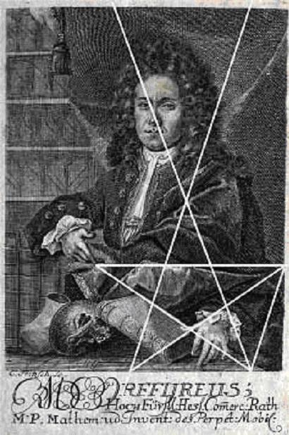
| Bessler's original portrait with pentagram added |
In 1712 Johann Bessler (aka ORFFYREUS) exhibited a machine which he claimed, drew its energy from gravity. Despite nearly twenty years of the most stringent tests, examinations and public trials, not the slightest sign of deception was ever found. Bessler died 33 years later, in poverty, still maintaining that his machine was genuine and there was no convincing evidence to the contrary.He had a number of supporters as well as enemies, and among his champions were some of the most respected men of the day. These men, included Gottfried Leibniz and Christian Wolff, top scientists of the calibre of Newton.
A
|
B
|
C
|
D
|
E
|
F
|
G
|
H
|
I/J
|
K
|
L
|
M
|
N
|
O
|
P
|
Q
|
R
|
S
|
T
|
U/V
|
W
|
X
|
Y
|
Z
|
Alphabetic substitution gives Orffyre from Bessler
Bessler wanted to sell his machine for the sum of £20,000, a fortune in those days, equivalent to well over a million Pounds today. Despite the apparent stupidity of asking such a large sum of money, it was not unique and in fact Bessler based the sum on the one offered by the British Board of Longitude, which, at the same time, was offering £20,000 to the first person to discover a means of locating the exact position of a ship at sea, longitudinally. John Harrison eventually won the money although it took him and his son many years to get all of it from a reluctant British government.
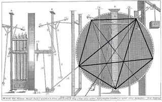 |
| First drawing of wheel with added pentagram, Grundlicher Bericht |
 |
| A picture of the remains of Bessler's windmill. |
Bessler failed to sell his machine, not for a lack of customers, but because he refused to allow access to his secret until he had the money in his possession. He offered his head to the axe man if he should be found to have deceived his prospective clients. But his determination not to risk being cheated of his reward, defeated all negotiations. He died in harrowing circumstances years later, building Northern Europe's first horizontal windmill to his own design of course. In mid-winter, starving, weak and in debt, he fell to his death. The massive base of the mill still stands, decaying, weatherworn and utterly neglected, in the small town of Fürstenberg in Germany.
 |
| Last page of Apologia Poetica with added pentagram |
The primary purpose of this blog is to discuss matters pertaining to the successful search for the solution to Bessler's wheel. There is good evidence that the inventor left behind him sufficient clues to permit someone to reconstruct the wheel. This information is formed from textual, graphic and encoded clues. On this page are examples of his hidden pentagrams but there are many more clues offering other hints as to the way his machine worked.
Other clues appearing throughout all of his works, implicate the number five. I have suggested that perhapst five mechanisms are needed to build a successful machine, but it may indicate a phase in deciphering his encoded material.
JC
10a2c5d26e15f6g7h10ik12l3m6n14o14r5s17tu6v5w4y4-3,’.


Just so as you know,..I'm still on track with good solid physics and should have a working wheel soon.
ReplyDeleteThere are five steps from the beginning to the end of the cycle which happens every half turn.
Therefore there are eight identical cycles in a full revolution.
Good luck Trevor! That would be a great end-of-the-year 2012.
DeleteYes indeed, good luck Trevor, but good luck to me too, as I might succeed before 2013 arrives, but I have only five mechanisms.
DeleteJC
John, please state, to the best of your knowledge, Bessler's intention behind the MT's. It may also be of value to list Bessler's publications, along with dates, in the order they were published. Thanks, Justsomeone
ReplyDeleteTo be honest jso, I don't know. I always called it the Maschinen Tracte because Bessler offered such an item to Peter the Great, Czar of Russia, but we don't know if this was the specific thing he had in mind or whether this MT was destined to be one of the tools he intended to use to teach the apprentices in his religion-based school.
ReplyDeleteI'll post a list of his publications but of course MT was never published. In the mean time you can find details at http://www.besslerwheel.com/wiki/index.php?title=Portal:Documents
JC
PART I:
ReplyDeleteOh boy! Another "look" to get used to. Well, at least the background color is not GREEN this time! LOL!
@ Justsomeone
It's obvious that MT was an effort by Bessler to document his AND others' various ideas about PM devices, to point out the problems with them, and, in the final pages which he destroyed, to present his students with the details of the mechanism he found which DID work. The fact that we even have something like this to study is almost miraculous, IMO (thanks, John!).
Well, my own research into Bessler's secret OB PM gravity wheel design continues and my recent decision to utilize cords that interconnect the 6:00 and 9:00 position weighted levers seems to be a good one. It allows me to provide the 9:00 going to 10:30 position weighted lever with extra lifting torque and, hopefully, this will finally allow me to achieve the "Bessler Effect" I seek which is a sudden direction change in the swing of the 9:00 position weighted lever's pivot as it passes the 9:00 position of a CW turning drum. Such a motion then causes the 9:00 position weighted lever's weight to begin rapidly approaching its rim stop as the lever's pivot approaches the 10:30 position.
During this afternoon's computer modeling session, I looked at my current "right track" wheel design and, once again, asked myself an important question: "Is this design 'So simple that a carpenter's boy could...etc., etc.'"? With each of my 8 weighted levers now having BOTH a primary AND a secondary spring attached to it and each secondary spring being replaced with TWO springs of half k value in parallel for a total of THREE springs per weighted lever, the answer was a resounding "NO!". So, I'm back to a SINGLE spring per weighted lever again.
But, there is a problem with using just one spring per weighted lever. This use would seem to directly conflict with my previous interpretation of that pesky "Parted Wig Clue" in the 1st DT portrait.
As many may recall, I had previously pointed out that there were 16 curls on each side of the wig Bessler wears in that portrait and that each of these represents a helical coil spring used in one of his two-directional wheels. I thought that the part in the wig (located by extending a vertical line upward from the inner corner of his left eye) represented the physical separation between the two one-directional "sub wheels" inside of his two-directional wheels which gave them the ability to be bi-directional. With each sub wheel containing 8 weighted levers and there being 16 helical springs in EACH sub wheel, the implication was that there had to be TWO springs assigned to EACH weighted lever which I came to refer to as the "primary" and "secondary" springs.
How then, could I justify just using ONE spring per weighted lever? The answer occurred to me this afternoon. Suppose that the PART in Bessler's wig does NOT represent the separation between TWO one-directional sub wheels with a two-directional wheel's drum, but, rather, represents a SPAN of TIME during which Bessler did NOT have a working two-directional wheel?!
PART II:
ReplyDeleteAfter reinterpreting the "Parted Wig Clue", I now think that it's possible that EACH side of the wig with its 16 helical coil spring symbols actually represents an ENTIRE two-directional wheel and that the two sides of the wig Bessler wears in the 1st DT portrait really represents TWO SEPARATE two-directional wheels which, of course, would be the Merseburg and the Weissenstein Castle or Kassel wheels! IF this is the correct interpretation, then Bessler is telling us here that EACH of these wheels only contained 16 springs that were distributed among its two one-directional sub wheels' 16 weighted levers; in other words, ONE spring was used PER weighted lever!
To further reinforce this new interpretation of the part in the "Parted Wig Clue" as actually representing the TIME between the destruction of the Merseburg wheel and the construction of the Kassel wheel, one can perform the following analysis.
It was noted above that the part in the wig could be located by drawing a vertical line upwards from the inner corner of BESSLER'S left eye. Now, using that corner of his eye as an origin, draw another line DOWNWARDS and bit to the left and make it intercept a noticeable "spot" on his chin which, I assume, was some sort of dimple (I happen to have an almost identical dimple on MY chin!). If one continues to extend the line through the dimple, it will eventually intersect the EXACT center of that little piece of jewelry that Bessler is wearing as a "keeper" on the end of the elongated end of the cloth piece that is wrapped around his neck which I guess is the early 18th century equivalent of a necktie. So, the keeper is equivalent to what we would call a tie bar. But, that little piece of jewelry is not just ornamental. It is probably some sort of "badge of office" which Bessler got to wear after Count Karl appointed him the Town Councilor for Hesse-Kassel which was a rather prestigious position considering Bessler's somewhat humble origin.
This connection between the badge of office Bessler wears in the 1st portrait and the part in his wig seems to indicate that, indeed, the part represents the time BETWEEN the destruction of the Merseburg wheel and the construction of the Kassel wheel which was the time that Bessler was appointed Town Councilor! Thus, EACH side of the parted wig represents an ENTIRE two-directional wheel and each of these contained 16 springs for its two one-directional sub wheels' 16 weighted levers or, again, ONE spring per weighted lever.
Phew!
Interesting. Your interpretations never cease to amaze me.
DeleteThanks, Anonymous 13:58.
DeleteI've been consistently trying to decode the DT portraits for several years now and am constantly being amazed at how a previous interpretation can be suddenly be cast into doubt when actual computer model testing shows it must be incorrect. Of course, Bessler also PURPOSELY put FALSE clues (which I call "decoy clues") into the portraits intended to frustrate and lead astray any reverse engineering mobilists. It takes a LOT of work to sort through all of this and find the valid clues and their correct interpretations. Occasionally, a single symbol can even have MULTIPLE meanings!
IF and when I finally find THE design and publish it, it will soon thereafter become apparent HOW I obtained the design from the portrait symbols. In fact, rather than deliver THAT information up on a silver platter to the denizens of PMland, I may just sit back and watch them discover it all for themselves which will not be too difficult to do once they also have THE design available for study.
Somewhere in one of his publications I remember Bessler saying something about giving " a complete history of the invention " which , I believe is the purpose of the MT .
ReplyDeleteJohn,.. I feel that the MT's were a record of all his failures,just to show how hard he had worked and where he had come from.
ReplyDeleteI think both of you, Chris and Trevor are correct. I was never completely satisfied with my use of the MT phrase as being the same thing as he promised the Czar, but there was no evidence of such a book in his records and I assumed that MT might have been part of it.
ReplyDeleteJC
What MT phrase are you referring to?
DeleteSorry, I was referring to the abbreviation for Maschinen Tracte = MT!
ReplyDeleteJC
Completely off-topic, John, but do you have any idea why (and/or when) Bessler fell out of grace with Karl?
DeleteJust wondering where we would be today if Bessler would have completed his notes for all the MT drawings. I have a theory that Bessler intentionally drew some of the MT wheels for the sole purpose of including parts of his working design. This may include several drawings. Signed Justsomeone
ReplyDeleteMy thoughts too. Bits and pieces of the truth here and there. So that someone "with a discerning eye..." et cetera.
DeleteHard to explain in a nut shell Andre, but here goes. Firstly, by 1722 he had had the benefit of Karl's patronage for tenyears, so he might have been thought to have outstayed his welcome.
ReplyDeleteSecondly he was Commercial Councillor assisting in bringing in trade and commerce to the region, but he was unfortunately being blackmailed by his former mother-in-law and his former brothers-in-law who were applying intense pressure on him to give money and goods to them.
His manner made him increasingly unpopular with other members of the Court and his former supporters had moved on to other regions or positions.
And of course his maid had made accusation against him which although roundly repudiated by Karl, left a doubts in people's minds which dented the reliability of his many examinations and testimonies.
Later on in 1726 Karl had begun to develop the symptoms of alzheimer's disease and his role as Landgrave was being increasing supported by one of his sons. Bessler was heard to make an unflattering remark about one of Karl's two mistrresses he acquired after his wife's death, and she spread more poison about him until his position became untenable. Karl released him with a house and gartden - and five years salary which he seems to have given to his mother-in-law.
JC
@JC
DeleteDo we know why Bessler was being blackmailed by his former Mother-in-law and Brother-in-law? Was it because they had seen the inside of the machine and were threatening to reveal how it worked if he didn't give them money and goods?
JW
In response to Andre's question, "...do you have any idea why (and/or when) Bessler fell out of grace with Karl?", JC wrote: "...by 1722 he had had the benefit of Karl's patronage for ten years, so he might have been thought to have outstayed his welcome."
DeleteJohn, I thought that Bessler had not met Karl until sometime (probably the summer) of 1716 AFTER the Merseburg wheel had been destroyed and, upon convincing Karl that he, Bessler, had, in fact, found a working OB PM gravity wheel design, then moved himself and his family into Weissenstein Castle before the end of that year at Karl's invitation. If so, they, by 1722, Bessler would only have received Karl's patronage for about 6 years.
I think the patronage relationship between Karl and Bessler began to seriously deteriorate AFTER the wheel at Weissenstein Castle was destroyed by Bessler on August 17th, 1721 because Bessler and his family were out of the castle before the end of that year.
I can just imagine how the count must have felt. He had been making consistent efforts using his prestige to bring potential buyers to see the castle wheel and telling them that it was, in fact, genuine in the hope of helping Bessler sell his invention. After meeting Bessler, however, many of those buyers or their representatives might have started to question Bessler's mental stability and wondered if they should risk their money on purchasing such a fantastic device or recommending that their employers do so. Then, to make matters as bad as possible, Bessler goes right ahead and does something which could only CONVINCE everyone that, indeed, he was a loon and, most likely, the invention was a hoax!
He DESTROYS the great wheel and then nobody really "buys" his explanation that he was just trying to keep the design from being stolen by Professor 's Gravensande. They see it as proof positive that Bessler was mentally unstable and his invention a hoax. Many may even have began to express pity for the count for having been taken in by such a clever hoaxer and, perhaps, even began to doubt the count's mental abilities due to his advancing age.
With the wheel gone, there was really no need for Bessler and his family to remain at the castle and the many people at court who Bessler had annoyed for years would have quickly seized upon this opportunity to get him and his family evicted. However, despite all of this, Karl KNEW that Bessler had a REAL working PM design. For that reason alone, he would have continued to support Bessler even though he might not have wanted him to do any further construction in HIS castle! (Sort of like loving one's relatives, but NOT wanting them to live NEXT DOOR to you! LOL!)
Sorry, TG, my head was elsewhere, 1716 to 1721 = about six years not ten. Bessler 'destroyed' his wheel prior to every move he made, most likely because it was the only way he could protect it during the move. This suggests that the move was already arranged and the house and garden which had only just been completed, were ready for him.
DeleteJohn, the blackmail had nothing to do with the wheel, but it is too complicated to explain here, but it concerns his deceased wife, and their daughter and his new relationship with his best friend's daughter.
On Bessler's best day , and at the height of his effort the world did not call him on his bet ( period ) . We ought not be blaming Bessler for his failure . I could care less about Bessler's personal life . I'm not saying that anyone is blaming bessler ... just stating my opinion . ( Update : ) I am several days into building my wheel .
Delete"I am several days into building my wheel."
DeleteHopefully, you will SOON have some "good" news to report!
It will be less than a month ( estimated worst case scenario ) .
DeleteAfter viewing the wheel, I believe Karl said something to the effect that it consisted of simple weights and levers. He might have had a different opinion if he saw it running, especially if cords and/or springs were involved and they were all moving.
ReplyDeleteDo we know either way (definitively) if Karl saw the wheel in motion?
I guess I should clarify, did Karl see the internal mechanism while the wheel was in motion.
DeleteSometime during the summer of 1716, Karl would have paid Bessler the 4,000 thalers (a silver coin used in the region whose name, interestingly, is the origin of our modern word "dollar"!) and, after pledging non-use and non-revelation of the design, been allowed to view the small 36 inch diameter prototype one-directional wheel that Bessler had made at the House of Richters in early 1712 that finally worked so that, upon the sight of it, Bessler's heart "leapt for joy". This model had all of the basic working components in it that, later, were scaled up for use in the Gera, Drashwitz, and Merseburg wheels.
DeleteThe count would have been able to study its parts and to see how its ascending side weighted levers would suddenly begin rotating CW about their pivots as these pivots passed the 9:00 position of the rotating wheel (I call this the "Bessler Effect"). Karl would have marveled at its intricate construction and observed how the weights whose lever pivots were moving between the CW rotating wheel's 9:00 and 3:00 positions would ALL continuously move closer to their rim stops as their pivots approached the wheel's 3:00 position.
This automatic action was the result of the various interconnecting strings between the weighted levers that served to both coordinated their motions with respect to each other and to transfer lost gravitational potential energy / mass from weights falling with respect to their rim stops to the ones on the ascending side that were rising with respect to their rim stops. Spring tension also played an important role in the action Karl observed. Most importantly, the count would have been amazed to find that this model wheel that Bessler revealed to him was SELF-starting. Thus, it was ALWAYS imbalanced regardless of the position the wheel was placed into.
So, Karl would have seen one of Bessler's one-directional wheels when it was stationary and when it was in motion. He would have had NO doubts that he was handling a GENUINE OB PM gravity wheel. Karl would also have been the only person aside from Bessler to observe the various phases of the construction of the Weissenstein Castle wheel. He would have seen the completion of its huge drum and the construction of the "magic" levers that would be placed into it before the layers of cloth were attached to its sides. He would have personally handled some of the lead weights that would finally be installed into the ready drum prior to it being tested.
Karl kept is pledge to Bessler and never revealed the details of what he had seen. All we know is that he is quoted as stating that the design was VERY simple and that he was SURPRISED that no one else had thought of it before Bessler! Bessler himself wrote that when the design was finally revealed, his detractors would merely say "...there isn't much artistry to it". In fact, it seems that Bessler was a bit embarrassed by the simplicity of the design and remarked that he felt whoever paid him the 100,000 thalers for it would feel like he had paid TOO MUCH for it!
Anon, the description of weights and levers comes from Frank Edward's book, 'Strangest of All', and has no basis in fact.
DeleteJC
Thanks JC. To your knowledge, are there any facts that Karl actually viewed the inside of the wheel while it was operating?
DeleteNot that specifically, although I strongly doubt that he would have been satisfied with just a view of the stationary insides. He could not state with complete honesty that he had seen the insides and it was very simple and it was genuine. He was an honest man with an important reputation to maintain and he simply wouldn't have accepted anything less than a demonstration which included seeing the mechanism in operation.
ReplyDeleteJC
He saw it , understood it and noted how simple it was . Bessler was a genius ...simple or not it was the first and only since .
DeleteI have to agree with your assessment. I'm not saying there weren't cords and springs and who knows what else, but if there were as TG suggests, I find it hard to image Karl making a statement about the simplicity of the design with so many cords and springs interconnecting the levers. When I look inside a piano and see all the wires, the last thing I think I would say is how simple the design looks. Just my opinion, and I am not in any way discrediting TG's work. Of course, back in those days, I think everyone was more mechanically inclined as everyone had to do for themselves (more than today anyway), so something we see as mechanically complicated may have been less complicated to them. This definitely holds for farmers. If you know any, they are really sharp. At least the ones I know.
ReplyDeleteThe word "simple" can, as you point out, be a rather subjective one, indeed. What one person considers simple another may find confusing and perplexing.
DeleteMy current "right track" design for a 4:1 scale model of one of the one-directional sub wheels used in Bessler's Merseburg wheel has 8 weighted levers (each having a 1 once lead weight at its end), 32 interconnecting cords, and 8 springs. That certainly sounds "simple" enough, but, as they say, "The Devil is in the details." The design I am working on requires a specially shaped lever (I call it the "magic" lever) which is NOT anything like the ones you will find in MT. There are precise points on these levers to which the cords, arranged into sets of 8 cords all having precise lengths, must be attached. The springs have to be attached from a specific point on the levers to particular spots inside of the drum and each has to have the correct spring constant or k value.
IF one finds the SAME design that Bessler used, he will be dealing with an array of weighted levers that are VERY delicately counter balanced with respect to each other. The fragile stability of their equilibrium is necessary in order for the active levers within a drum to automatically begin shifting about their pivots as drum rotation proceeds in such a way that the CoM of the 8 weights will remain on the drum's descending side. Even with the abundance of clues given us in the two DT portraits, finding THE precise set of parameters Bessler found and used is a MONUMENTAL undertaking. I've been at it for YEARS and only recently feel like I'm even starting to see some light at the end of the tunnel. I still have MANY questions I need answers to before I can legitimately declare success.
For example, I recently realized that "simple" MUST mean ONE spring per weighted lever. BUT, should I use the previous "primary" springs OR the "secondary" springs that I found clues for in the DT portraits? The DT portrait clues give information about BOTH types of springs, but only the information about one type is correct and the other is a "decoy" clue to confuse reverse engineering mobilists! That means I have to construct models using BOTH types of springs and to a lot of testing to see which one works best.
Next, did the descending side weights make contact with their rim stops BEFORE or AFTER their lever pivots passed the 3:00 position of the rotating drum? Again, the DT portrait clues provide information on BOTH possibilities amd I must construct models using both options to see which is best.
I recently discovered that my "magic" lever design, which I was previously convinced was 100% correct might actually have a flaw in it that requires me to rotate a section of it a further 2.5 degrees. That means that I will have to construct a new set of 8 levers to cover this possibility and then test them. All such modifications take time, effort, and much testing. This is why the SERIOUS active reverse engineering Bessler mobilist had better plan on investing YEARS to finally uncover the design that Bessler found and used even with the aid of the technical data encoded into the two portraits.
Many think that they will surely find THE solution by piecing together bits and pieces of MT drawings. All I can say to that is that if one puts together bits and pieces of designs that do NOT work, then he should not expect to get anything out of it other than another design that will NOT work! To make REAL progress you need PRECISE mathematical information about the components ACTUALLY used in Bessler's wheels. The only place you will find that is in the DT portraits, but it won't be served up to you on a silver platter. You will have to WORK for it and work DAMN hard!
It was/is simple . Simple is simple . The movement of our solar system is simple , it's constituent parts and elements are complex . Relativity is simple , chemistry not . Get it ?
Delete@ Anon
ReplyDelete"but if there were as TG suggests, I find it hard to image Karl making a statement about the simplicity of the design with so many cords and springs interconnecting the levers"
Yes, That is my opinion too Anon,
JW
Each of the weighted levers only has four cords attached to it to lift it when it is on the ascending side of the drum. Three cords go to other levers and one cord goes to a spring. It is NOT complicated, but the levers must have a precise shape, each weighted lever must have a particular starting orientation at the beginning of each 45 degree increment of drum rotation, the cords must be certain lengths, and, lastly, the springs must have a certain spring constant or k value. The appearance of the design is DECEPTIVELY simple and hides the tremendous amount of labor that Bessler had to perform in order to find the correct parameters for all of these components. Anyone who wants to duplicate his achievement will literally have to REPEAT everything he did INCLUDING his missteps along the way! Those missteps are there in the two DT portraits in the form of "decoy" clues and there are many of them.
DeleteThanks JW, I was beginning to think I was the only person thinking this way. Of course, maybe I am envisioning an overly complicated design.
ReplyDeleteTG, any chance you can draw up something (of course make any alterations to your magic levers and any pinned points you feel you need to hide) so we can get some visual idea of what you are suggesting with the cords and springs? You've given an enormous amount of details about the design, so much so, that it is hard to picture. Not asking for any confidential information here. This might be a good exercise for you. If while creating, you find the design being too complicated, you may want to re-visit your interpretations as you are now doing with the springs.
As they say, a picture is worth a thousand words. And when you say a thousand words, I mean it ...
DeleteWhy? It won't work.
DeleteI will only reveal the complete details of my "right track" design IF I can get it working. Those details will include the "magic" lever shape, the Connectedness Principle scheme of cords, and the correct locations of the springs within the drum. Unfortunately, now is not the time to reveal anything because I am not yet 100% of the way to the end of the "right track" with a working design. Now is the time for me to concentrate on getting a WORKING design so that I will have something to reveal that others can base their physical models on with some hope of them actually working.
DeleteIs there an MT illustration that approximates the way the cords are run so we can get an idea of the basic design (according to your interpretations of the portraits of course). My interest isn't so much with the springs or levers but with all the cords and how simple it might or might not look. Right now I am envisioning a bowl of spaghetti.
Deletehttp://www.peppertop.com/polygon_web.svg
Deletehttp://www.inkscapeforum.com/viewtopic.php?f=5&t=9519
DeleteYep that looks pretty "Right Track" to me.
DeleteSpeaking of MT.........John, do you know the only English word that ends in MT? It may just be appropriate. Justsomeone
ReplyDeleteDon’t hold me in contempt for I will not attempt to preempt JC.
DeleteVery good Anon. Lol. Justsomeone
Delete@TG
ReplyDelete“Many think that they will surely find THE solution by piecing together bits and pieces of MT drawings. All I can say to that is that if one puts together bits and pieces of designs that do NOT work, then he should not expect to get anything out of it other than another design that will NOT work!”
TG You really do have a bad habit of being badly wrong.
You have completely missed the point of the MT Clue Images; what Bessler was up to with his ridiculous, completely implausible, ‘toy-town’ creations. He was ‘having a laugh’ the ‘mechanisms’ are a joke. Each image (MT9-140) is nothing more or less than an excuse for a visual clue, or two, or three!
The pictures are not the record of some failed design or experiment.
For example MT102, What record of a failed machine is this with all its wheels binding on the inclined bed? No one would ever have built it. And what is MT98 with a river and a house in it? You are not allowed to use rivers in OB PM machine designs. And what is MT107 all about? According to you these are all the records of either Bessler’s or someone else’s serious attempt at building an OB PM machine are they? I think you need to think again.
His method is one of abstract presentation as opposed to the figurative presentation you seem to assume he is making.
To “find the solution by piecing together bits and pieces of MT drawings” is not really adequate as a description of what is involved, but it is as a notion essentially correct.
JW
"His method is one of abstract presentation as opposed to the figurative presentation you seem to assume he is making."
DeleteEr...I think we are going to have to agree to DISagree about this!
Well said JW. I think the illustrations are for learning purposes, maybe like hypothetical problems in a math book. Maybe not the best comparison but its all I've got at the moment.
ReplyDeleteThe only English word ending in MT is........................DREAMT. Hmmmmmm... Justsomeone
ReplyDeleteVery good JSO!
DeleteJC
There is one question from Bessler's time that I'd really like to see answered. It would have been easily answered back then, but the information may be lost now:—
ReplyDeleteWere all of Bessler's wheels oriented approximately in an East-West plane, i.e. with their axles running North-South?
If they were, that would be a strong clue that he was extracting energy from the Earth's rotation. If we knew for sure that even one of them wasn't, then I think that theory would have to be discarded.
They weren't extracting energy from earth's rotation in any plane.
DeleteFrames of reference.
Doug
It might be possible to determine the orientation of the Weissenstein Castle wheel.
DeleteSimply obtain a surveillance satellite view of the former site of the castle and try to determine the orientation of its front wall. Most likely the room that contained Bessler's wheel was located on the second floor and had a window that faced into the courtyard behind the castle's front wall so that a rope around the wheel's axle could go directly out of the opened window to hoist loads up from the courtyard below. This means that the axle of the wheel would have had the SAME alignment as did the front wall of the castle. IF the front wall faced EAST so that it would catch the rays of the rising Sun, then the axle of the wheel would have been aligned north to south.
I'm with Trevor on this one.
DeleteJC
JC wrote: "I'm with Trevor on this one."
DeleteTrevor did not comment on Arktos' comment. Did you mean that you agreed with MY comment's suggestion?
Sorry - Doug, not Trevor.
DeleteJC
@TG, At least that's a constructive suggestion. I had a look at the map at http://mapcarta.com/17969358. If that's the correct part of Weissenstein castle, and the map is "North up", there is a long wall running East-West. If the wheel was installed in a room along that wall, it would have to be oriented North-South to get the rope out of the window, and my theory fails. But there are also two shorter walls running North-South, joined to the longer one, and if the wheel was installed in a room along one of those, the theory is still alive.
DeleteThe wheel was totally independant of the earth's gyroscopic effect or the angular momentum.
ReplyDeleteI sense an aire of desperation here.
OK, I'll spell out a couple of steps towards the kind of machine I have in mind.
ReplyDelete1. As Doug says: "frames". In a laboratory frame, rotating with Earth, at the equator, take a 10kg mass, place it at the eastern end of a spring, whose western end is firmly fixed to Earth. Compress the spring so that it stores 50 joules of energy, then release it against the mass. All the stored spring energy is given to the mass, which means it accelerates to about 3.16m/s.
Now do the exact same experiment, but this time do the measurements in a non-rotating frame, still moving along with Earth's center. In such a frame the mass starts with 465.1m/s, and reaches (465.1+3.16) = 468.26m/s. So it goes from 1081590 to 1096337 joules, i.e. now it gains 14747 joules, far more than before.
2. The standard objection:— "You can dream up any frame you like, but as long as you can't get at it and do things in it, it's all just mathematical sleight of hand." True, but there are two frames that can be "got at" however briefly: the forward-moving and backward-moving parts of the wheel, provided the wheel is in an East-West plane.
So far I can get about 100 watts from an admittedly large and "high-tech" [computer model] wheel of this kind.
How does the 10 kg mass start with more m/s in the second experiment? Any experiment on earth is fixed to its frame of reference, going at that speed. The spring, the mass, the lab. You'd have to do the experiment in space to change the frame. But everything in the space lab is going at the same speed; so you're back where you started.
DeleteYou can't mechanically convert the rotational energy of the earth without another reference to be "got at".
Tidal power isn't a result of the earth's rotation.
Can you demonstrate some sort of gain using a practical model.More importantly,would it be wise to exploit anything that would have the slightest effect on the revolution of the earth.
ReplyDeleteWhat are your thoughts?
@ Trevor, No, I'm still a very long way away from any practical model. It would be even harder (probably really impossible) to turn this idea as it is currently, into an economically viable machine.
DeleteAs for the general question of taking energy from Earth, I've mentioned the tidal power schemes before, which strictly speaking take energy not only from the Earth, but also the moon and sun. Some, e.g. Rance (240MW) and Sihwa Lake (254 MW) are aleady operating. Russia is planning at least two much bigger ones, at Mezenskaya, and the 87,100MW Penzhinskaya scheme.
With random tidal movement and the fact that whatever mass goes up must inevitably come down,would this not cancel out in anycase?
ReplyDeleteNo, the tidal movement isn't random. Google "Rance tidal power" for example.
DeleteLook at it this way,..Every action has an equal and opposite reaction.
ReplyDeleteWith a body suspended in space...There is nothing you can do to propel yourself or cause you to revolve.Each action cancels out.
Of course ejecting a mass from the body will cause an effect.
Forgive me for straying off topic!
On the contrary, you are on topic.
Delete"With a body suspended in space...There is nothing you can do to propel yourself or cause you to revolve.Each action cancels out."
Exactly. In a wheel, there is nothing it can do to cause itself to revolve, short of ejecting mass (until it disappeared, hypothetically speaking).
Sorry Doug,..With the wheel it's different.You have gravity to draw on using mass.
Delete@ Trevor and Doug, I agree with you about a body (a wheel) suspended in space. My point is that what we call a laboratory frame, in which we do our experiments on Earth, is attached to, and rotating with Earth. That can be exploited; how well remains to be seen.
DeleteImagine a wheel on a vertical axis at the equator. It is spinning so fast that the westward-moving part of its rim reaches -465.1m/s in the laboratory frame, i.e. zero m/s in the non-rotating frame. So then the eastward-moving part of its rim reaches +465.1m/s in the laboratory frame, i.e. 930.2m/s in the non-rotating frame. That makes that portion of the rim lighter. The amount works out to be 0.1357 newtons per kg.
That difference can be exploited. One crude, probably impractical way would be to have the rim segmented, with each segment able to move vertically, one oscillation per wheel revolution. I've modelled that, and get about 100 watts out for a flywheel of about 1000kg.
"wheel on a vertical axis at the equator....the westward-moving part of its rim reaches -465.1m/s in the laboratory frame, i.e. zero m/s in the non-rotating frame. So then the eastward-moving part of its rim reaches +465.1m/s in the laboratory frame, i.e. 930.2m/s in the non-rotating frame. That makes that portion of the rim lighter."
DeleteThis must be new physics!
No, it's a varying centrifugal force, opposing the weight of the mass. F = mv²/r.
DeleteIn the non-rotating frame moving along with Earth's center, consider a 1kg portion of the wheel's rim. Assume Earth's equatorial radius is 6378137 meters:—
F = 1 × 0²/6378137 = 0 when the mass is at zero m/s.
F = 1 × 930.2²/6378137 = 0.1357 newtons when the mass is at 930.2 m/s.
(Note also that F = 1 × 465.1²/6378137 = 0.0339 newtons when the mass is at 465.1 m/s, i.e. at rest in the laboratory frame).
So an observer in the laboratory frame, which is what matters, would see a reduction in the weight of that portion of the rim moving eastward, and a (smaller) increase in weight in the portion moving westward. Remember that the laboratory frame is not a perfect inertial frame assumed by Newtonian mechanics.
Very interesting experiments, Arktos!
DeleteThanks, Andre. So far, I think I'm just "scratching the surface" of exploiting Earth's rotational energy. There are other ways of attacking this problem, but I want to do more work on them before talking about them.
DeleteInstead of trying to tap the Earth's rotational energy, I think that there is plenty of "clean" energy in and passing through our atmosphere that can be used such as wind power and solar power. But, the recent fossil fuel "Energy Boom" around the world will probably slow the evolution of those technologies while we continue to extract the last drop of oil and cubic foot of gas from our planet's crust and more and more carbon gets dumped into our overheating atmosphere. Maybe we should be trying to figure out ways of using fossil fuels WITHOUT allowing their oxidized carbon and soot particles to fly off into the air? Right now people want as many kilowatt hours as possible for their dollar and that, quite unfortunately, can only be achieved by NOT cleaning up emissions or switching to "renewable" forms of power. We are in a real bind.
ReplyDeleteMeanwhile, the east coast of the US may be battered by "superstorms" EVERY year (I'm stocking up on candles, batteries, and non-perishable foods!). I even heard on the news that western Britain is now flooded out from some of the worst rains they've had in decades. It just seems like the extremes of weather continue to get more extreme. So far, however, it has not yet gotten bad enough so that the "political will" to do something about it exists on a GLOBAL level. Maybe in another decade that will finally happen. Expect to see more and more about these issues in the news in the coming years.
As far as Bessler's wheels are concerned, they did NOT utilize the Earth's rotation for their operation and the orientation of their axles with respect to the Earth axis of rotation was irrelevant. All that was important for their operation was that their axles were perpendicular to the Earth's gravity field. Actually, they would still work if their axles were tilted a bit from this orientation, but that would then reduce their axle's torque and output power. Remember that Bessler wanted to use one of his wheels to drive a boat. That would not be possible if the wheel only worked with certain orientations with respect to the Earth's axis of rotation.
With this morning's computer modeling session, I saw a "first" in my design. As the model drum rotated through an increment of 45 degrees, I managed to have the 9:00 going to 10:30 SUDDENLY fly up so its weight rapidly approached its rim stop while the 7:30 going to 9:00 position weighted lever's weight just as rapidly dropped away from its rim stop. When this unexpected and quite violent action took place, the CoM of the wheel's 8 weights quickly jerked way over onto the drum's descending side. I must admit that I was a bit shocked by this motion, but, at this point, am not going to get too enthusiastic about it. I will, however, continue to explore the potential of the design. Most importantly, this violent shifting action only used ONE spring which, as I suspected, was ALL that was required by the weighted levers inside of Bessler's wheels.
The design I have, despite this recent impressive shifting action, still does not keep the CoM of its 8 weights on the drum's descending side THROUGHOUT the 45 degree increment of rotation so there is still plenty to do. I do, however, feel like I'm getting closer to the end of the "right track". I'm still feeling "good" about the possibility of success by THIS Christmas.
@ Doug, see my reply 19:29 below.
ReplyDeleteThat should have gone under Doug's comment at 13:39. Sorry.
Delete@TG
ReplyDeleteCan you tell us what MT design (if any) that has cording similar to the design in your latest interpretation?
PART I:
DeleteSadly, NONE of the MT designs has the correct "Connectedness Principle" cord scheme shown in it. However, MUCH can be learned from what Bessler considered the "good" principle illustrated in MT 10.
What is so "good" about it?
Note that as the weights pass the 9:00 position, they are SIMULTANEOUSLY lifted up by the cords connecting them to the weighted levers that lead them AND by their contact with the curved levers that lag them. Here Bessler is telling us that THE design he found and used relies upon torques being applied to the weighted levers whose pivots are passing the 9:00 position of a CW rotating drum by the weighted levers that BOTH lead AND lag behind them.
MT 14 is also important and Bessler even promises that he will show "how it can and may be used" later in his text. Here we see that there can be interconnections between two weighted levers that are NOT adjacent to each other.
Again, I am quite convinced (now!) that this principle was used in Bessler's design and I've recently committed myself to using it in my designs by having my 9:00 going to 10:30 weighted lever also being lifted by the 6:00 going to 7:30 weighted lever (as well, of course, as the 7:30 going to 9:00 weighted lever which immediately lags the 9:00 going to 10:30 weighted lever).
I even continue to still wrestle with the importance that spring tension played in Bessler's wheels. His two DT portraits are filled with spring symbols (remember the "Parted Wig Clue" in the 1st portrait?) and I have been using them for months with, unfortunately, little success. In fact, only a few hours ago I was testing a design that worked fairly well (but still did not maintain continuous OB of its weights' CoM throughout the 45 degree increment of drum rotation), yet used NO springs!!!
It's entirely possible that all of those spring symbols in the DT portraits may, indeed, be "decoy" clues designed to lead the reverse engineering Bessler mobilist astray by getting him involved in the extra complexity of dealing with spring tensions inside of his designs. Indeed, I've noted that whenever I am using a falling weight's lost gravitational potential energy / mass to stretch a spring and, thereby transfer the falling weight's energy / mass to the spring, that means that I DON'T then have that energy / mass to DIRECTLY and more immediately raise another weight and thereby increase its gravitational potential energy / mass. So, I am starting to wonder just how important the springs really were in Bessler's wheels although I intend to continue to use them for the time being.
PART II:
DeleteIn MT 18 Bessler illustrates the use of a tapered strip type of spring (not linear) in a wheel. The spring is progressively flexed on the ascending side of the wheel by its falling weight and then relaxes on the descending side as it propels its attached weight back up to its resting place on its rim stop. He tells us the design does NOT work and then adds:
"In the meantime, the principle should not be disdained or entirely disregarded, for it says more than it shows. I, however, will show more than speak of it at the appropriate place."
Telling us that we should not "entirely disregard" the illustrated principle does not really seem to put much of an emphasis on its importance. It's possible that the springs inside of Bessler wheels ONLY served the function of keeping the EMPTY levers in place against their radial drum support member stops when Bessler was translocating a wheel and, thus, played almost no role in shifting the weighted levers about during drum rotation! The use of the springs to provide some SMALL amount of spring tension would have been necessary to keep the unloaded levers from swinging about and getting all of their interconnecting cords tangled up which would have been a real headache to straighten out before the weights could be reattached to the ends of the levers so that a demonstration could be continued.
Well, these are all matters that will require MUCH future modeling and testing to sort out. In the meantime, I'm in the process of slightly modifying my "magic" lever's shape to bring it into agreement with a newly discovered DT portrait clue that seems valid (at this point in time!).
The nice thing that will come out of finally finding THE design that Bessler used is that it will immediately make the various symbols used in the portraits understandable and will separate the valid ones from the "decoy" ones. It should also help remove ambiguities in the text translations and indicate which portions of text have been poorly translated.
From your explanations so far, TG, I can see that these springs (both in shapes and K-value) are extremely delicate and critical. This makes me wonder: did Bessler in his day have the tools and knowledge to design, construct and measure such precise components?
Delete@ Andre
DeleteDon't forget that Bessler was also a skilled clockmaker. That craft required the construction of precisely shaped components and use of springs with presise k values. Tolerances to 1/100th of an inch were easily obtainable. Bessler most certainly would have applied the skills that he acquired from clock and organmaking to the construction of his wheels.
" Bessler failed to sell his machine, not for a lack of customers, but because he refused to allow access to his secret until he had the money in his possession."
ReplyDeleteWhen you are selling something you cannot give it away and still expect someone to pay you for it . The above quote fails to make any sense to me . Also ( contrarily ) I believe that Bessler didn't sell his machine because the world did not value it enough at the time in order to pay for it . Everyone seems to down Bessler for protecting himself .
If you'd read my book you'd make sense of the comment Chris. There I explained fully why he could not afford to allow anyone access to his secret until he had been paid. I wasn't criticising his action at all, just telling in brief what happened.
ReplyDeleteJC
I vaguely recall reading somewhere that Bessler proposed a sort of escrow method of payment for his invention. The buyer would give Count Karl the 100,000 thalers to hold and would then recieve the invention. The buyer would then analyze and test it to verify that, indeed, it was a genuine OB PM gravity wheel. Once the buyer acknowledged that fact, the count would turn the money over to Bessler. IF, OTOH, the buyer discovered that the invention was a fraud, Karl would return his money to him along with Bessler's severed head! Sounds fair to me! LOL!
DeleteYou're half right TG. The escrow method was one that had been suggested by Christian Wolff, but as Schumacher put it, (he was negotiasting to buy the secret for Peter the Great) Bessler says 'put the money on the table and take the wheel', and if I negotiated for a year he wouldn't give way one bit. Something like that any way.
DeleteJC
Lol , cause and effect . He didn't sell it because he didn't give it away . The fact is nobody put the money on the table . His " buyers/customers " never paid . I completely understand why he couldn't give it away or let anyone see it . I have heard people openly criticize Bessler for his " antics " and other things . The above sounds no different to me . If you were implying that the design was too simple to be shared without compromising the whole discovery you could have said that . The reason I haven't bought anymore of your books is because when I lost my digital copy of DT I asked you for another copy and you ignored me ... but that's beside the point .
ReplyDeleteAnd just to drive my point home let me add ... just email me the book ( whichever one I was supposed to have read ) and trust that I will pay you . Technology/mechanics isn't like a book where you get a little sample and then you're interested or not and decide to buy or not . Bessler tried all legitimate ways to sell his invention . It was the world at large that failed , not Bessler . Nothing short of piracy is what Bessler was guarding against .
DeleteAnd also , soon all questions will be answered anyway so none of this matters .
DeleteBessler said his wheels worked on different principles. I don't think (as TG suggests) that putting two one directional wheels (of the same principle) back to back so you have a bi-directional wheel is what Bessler meant. I believe MT includes bits and pieces of multiple designs that work, requiring a discerning mind to pull all pieces together. I have found 3 such designs in MT that I am pursuing. Best of luck to you. Rick
DeleteJohn.
ReplyDeleteNo offense intended and I know you are trying to promote research into Bessler . I also know that you mean no harm . But what's to keep the average reader from reaching the same conclusion I did in this case ? " Bessler failed to sell his machine, not for a lack of customers, but because he refused to allow access to his secret until he had the money in his possession " is
a pretty straight forward statement that implies that if he had disclosed the secret to a serious buyer the buyer would then have been motivated moreso to lay the money down . Have you emailed that book yet ?
If we can't find a way to increase the power of the wheel using today's materials and technology, then I doubt if Bessler's wheel would be received well during our time. Yesterday I stood next to a large circulation fan at one of our factories and seemed at least two stories tall. If that was Bessler's wheel and it could only lift 70lbs, and I had to have many of these just to power the lights in my house, well I probably wouldn't. Communities all across the country (USA) are trying to ban or regulate the placement of satellite dishes and solar panels on houses. Can you image what would happen if someone put 20 12' wheels in their backyard.
ReplyDeleteA couple of months ago we were discussing the use of Bessler wheel powered electrical generators to power high efficiency all electric homes. My calculations indicated that an entire block of houses could be powered by a single wheel. Unfortunately, the wheel had to be about 100 feet in diameter and have one ton weights in it! Just imagine the problems with trying to install and maintain one of these giant monstrosities on EVERY block in a town!
DeleteAnyway, while I don't yet see Bessler's wheels as being potentially "commercially viable" as far as electrical power generation is concerned, I certainly do think that they are an important part of the history of science and a mystery that should be solved.
Chris you always say no offense intended, just after you've caused offence. I have paid very little attention to your words ever since you begged me to review your design many months ago and I refused more than once, for very good reasons. If you had a design I was already working on, seeing yours would put me in a difficult position. Nevertheless I finally agtreed to review it, warning you that I would be honest and if I thought it was not a valid design I would say so, and you agreed to accept my opinion. But what a song and dance followed my negative review! You were extremely offensive for some considerable time and I vowed never ever to review another person's design no matter how they pleaded with me. Now you say I ignored your request for a free book, well if I did no wonder! But I have no recollection of seeing such a request but then, as I say, I don't bother to read much of what you write. Your interpretation of my words are completely mystifying to me hut then you have so little regard for me that I should not be surprised.
ReplyDeleteJC
You write nonsense and then when someone asks you to elaborate or clarify something you say they can't understand your English without reading more of it . I never asked for a free book . My designs and yours will never be the same . I don't dance BTW .
ReplyDeleteChris, why buy the cow if you get the milk for free? Bessler did not have patent protection so if he disclosed the secret there would be no reason to hand over the cash. They could just go and build it. Justsomeone
ReplyDeleteCorrect, but not disclosing it was not the reason he didn't sell it .
DeleteSurely it must be overdue for Mr. Wilson to declare he is never going to post on here ever again ..........PLEASE!!!
ReplyDeleteMeanwhile, I'm happy to report that I just finished the modification of the "magic" lever design I have and will soon be using it in my "right track" computer model wheels.
ReplyDeleteI intend to try variations that both use and DON'T use springs to assist in the lifting of the ascending side weighted levers. Then I'll try designs that have the weighted levers' weights alighting on their rim stops before and after their lever's pivots pass the 3:00 position. I will also have to make a slight modification in the "Connectedness Principle" I am using based upon my having recently added a cord to interconnect the weighted levers that are 90 degrees apart (thus 8 more cords must be added to the one-directional wheel). Maybe these changes, all suggested by recent new interpretations of some of the more puzzling of the DT portrait clues, will propel me that last 0.01% of the way to the end of the "right track" and this mystery can FINALLY be solved!
I've noticed a bizarre kind of "duality" in the way Bessler presents clues in the DT portraits. Often a single clue will have two distinct interpretations, an obvious one and a somewhat less obvious or even hidden one, and the reverse engineering Bessler mobilist must, via careful construction and testing, determine which of the two is the valid clue and which is the "decoy" or false clue. Since there are a least a dozen technical details that go into arranging and constructing the components necessary to replicate one of Bessler's one-directional wheels, that means that if each detail is covered by one clue with TWO possible interpretations, then one has 2 to the 12th power or 2 x 2 x 2 x 2 x 2 x 2 x 2 x 2 x 2 x 2 x 2 x 2 = 4,096 possible combinations of valid AND false clues to consider and only ONE of them (containing ONLY the valid clues) will lead to the exact same design that Bessler found and used!
If one had all two dozen DT portrait clues (all valid and invalid interpretations together, that is) written out in front of him and picked a dozen out of them at random to base a wheel's construction on, then he would only have a 1 in 4,096 chance of picking the correct one. There are daily lottery games that give one better odds of a win than that!
This, of course, is all part of the elaborate measures that Bessler went to in order to secure priority to his invention while still maintaining maximum security on the design. In the two DT portraits, the solution is presented in enough detail to allow replication, but one must be able to untangle a virtual Gordian Knot of symbols in order to do so!
dear John I'm new to all this computer lark, so if I've contacted you in the wrong way I appologise.I read your book years ago and like most people I ponder on the workings of the wheel, well the other day I thought the only thing that most people don't pay attetion to is the axle.I also thought that Bessler may have come up with the idea of a Milkovic oscillator first, so I set about designing a wheel that combined both.As you know the oscillator needs to work on a fixed pivot so I designed an an axle that is fixed in the middle but turns on the two outer sections. This allows the wheel to turn but provides a fixed point for the oscillator.I made a few drawings , and wanted to post them to you but you no longer use your P.O. box.I will try to describe my idea in words.Basically it is two basic 8 spoked wheels with a third wheel sandwiched in the middle, the inside of the middle wheel has ratchet teeth on the inside plus 8 larger lobes around it's cicumference.On the end of the oscillator arm is a ratcet dog, this works on the inner wheel teeth.When the oscillator is moving it ratchets the whole 3 part wheel around until the 11 o'clock weight tips. the wheel then turns , trying to find it's equilibrium, as the turning occurs the larger lobe strikes a side extension arm on the oscillator pendulum, and starts the process again.The wheel is simply started by turning it, the ratchet dog will be free, but the larger lobe will strike the side extension arm.If you would like to see the drawings I can be contacted at P.O. Box LB 09 , Laborie, St. Lucia, West Indies, ZSLC 03. Regards, Stephen Burke.
ReplyDeleteJohn I've had a little time to think about my Milkovic oscillator idea, and now I realize that the oscillator pendulum would probably run out of momentum before the 11o'clock weight got to it's tipping point,so a little more thinking and I came up with this.Bessler based his wheel on a seige catapult, I put the two together plus what can be seen on the outside of Bessler's wheel and came to this scenario.The Milkovic oscillator partially turns the wheel, this moves the 11o'clock weight nearer to it's tipping point , but also raises one of the external cam lifted weights, this weight pulls the wheel in the reverse direction putting tension on it.The two external pendulums are on their downswing, and being as they are connected to the axle they are so arranged as to be applying a force in the direction of rotation.Now if just before the last purposeful lift of the Milkovic oscillator the external cam lifted weight is dropped, TWANG! ,the wheel, weights the whole kit and kaboodle is shot forward thus passing the tipping point, the ratchet wheel lobe striking the pendulum on the Milkovic oscillator setting the whole thing of again.Now the $64,000 question, what does my axle look like ? All I will tell you is, it fits perfectly with Bessler's drawings,it has the reduced diameter at both ends,it can drive the two external pendulums,it lets the wheel spin and has a fixed centre piece so that the Milkovic oscillator can be anchored and not turn with the wheel.Why am I being secretive ? that will be between myself and John, after all his hard work and inspiration, not to mention perspiration ! I don't want some idiot jumping the gun and getting all the glory.Also as you all know you cannot patent a perpetual motion device, and Mr. Milkovic probably has a patent on his 2 stage oscillator,although if it can be seen openly on the internet, is it in the public domain ? However , I can patent my axle design.Regards Stephen Burke
ReplyDeleteHi Stephen, the best way to contact me is to email me at jcollins at free-energy.co.uk.
ReplyDeleteJC
OK John I've never e mailed anybody in my life ! Yeah I know a real dinosaur.I'll find someone a bit more savvy and get them to scan the drawings and send them to you. I don't have a scanner anyway. Steve.
Delete